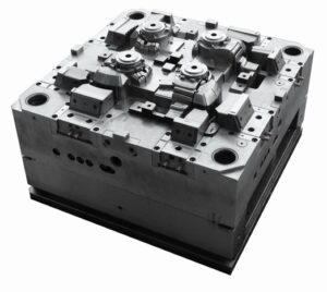
How does an injection tool help in investment casting?
Investing in injection tool
Generally, much of the product cost goes to making the mold for the injection tool. If the product has a short life cycle or low demand, investing in a durable form can be more expensive than using a 3D printer.
Limitations in making changes to the design of the part
After the manufacture of the mold, it is difficult to make changes in the design of the part without significant costs to change the design of the mold and increase the time to manufacture the latter. If you have not yet decided on the design of the product (Injection tool) then it is better to use 3D modeling until the design is finally approved.
Features of injection mold
Some of the most common features of injection molding include:
- First, production of large volumes of products.
- Second, quality plastic products require precision and consistency.
- Moreover, projects with a long implementation time.
- Lastly, production of any details, from the smallest and small to difficult and large.
3D printing working
3D printing uses computer-aided design (CAD) files to build three-dimensional details layer by layer. The 3D printer uses a heated thread to create vertical layers that overlap; this creates a single product at a time.
Benefits of using 3D printing
1-Low initial cost
No special stamps or molds are common for 3D printing of the Injection tool. Once the product design is complete, the printer can create one or hundreds of finished parts at the same unit cost.
2-Ability to make changes to the configuration of part
Since a computer file is common instead of a mold, 3D printers can easily apply product changes to the design. This is ideal for prototyping when your team is testing different designs and different stages.
Disadvantages of the 3D printing
1-Technical nuances in tools
3D printing is an evolving science. Software and hardware sometimes fail, which can lead to errors and poor quality of the structure.
2-Speed of 3D printing
3D printing creates layer by layer, one product at a time. This is the most efficient way to make orders of up to 100 units. If you need to make more parts of the Injection tool, then this method becomes economically costly.
3-Product quality by 3D printer
3D printing can create structural defects during manufacture, which usually do not occur when casting plastics under pressure.
Features of injection mold
3D printing is common for:
- Firstly, prototyping and testing
- Second, with a small production volume
- Moreover, testing of the individually designed product
- Manufacture of products, the structure of which is often changed or updated
An overview of injection molding implementation
When injection molding, each error is usually very expensive. Quality problems in cast products are reflected in the form of minor surface defects. Or more serious damage to the Injection tool that can affect the safety, performance, and functionality of the product.
They can be common by problems related to the casting process, the use of materials, the design of the tools, or a combination of all three factors. But like any quality problem, knowing how casting defects occur is a partially won battle.
Recommendations for injection molding
Individual recommendations and knowledge about common casting defects and how to avoid them can help you reduce the costs associated with the goods. Consider the most common defects that occur during injection molding, as well as determine what causes them and what can be done to avoid them.
Reasons for injection molding defects
Some casting (Injection tool) defects can be difficult or expensive to repair. Others can be prevented by regulating the casting process, without the need to recycle the mold or replace other production equipment. You can usually avoid these defects relatively easily by simply adjusting the material consumption, temperature, or pressure of your mold.
Separation due to injection tool
Separation often looks like wavy patterns, slightly different in color than the general area, and usually on narrower areas of the molded component. They can also be annular strips on the surface of the product near the injection points of the mold or “gate” of the gutter system.
Through which flow the molten material, Injection tool. Separation lines usually do not affect the integrity of the part. However, they have an unaesthetic appearance and maybe unacceptable if they can be seen on the finished product, such as sunglasses.
Causes and means of eliminating divorces and lines
Divorces and flow lines most often occur because of fluctuations in the cooling rate of the material, because it flows in different directions throughout the form. Differences in wall thickness can also cause the material to cool at different speeds, leaving flow lines.
For example, the Injection tool cools very quickly during the injection process, and traces of flow are visible when the rate of introduction of the material is too slow. The plastic becomes partially hard and sticky while filling the mold, causing a wavy pattern.
Here are some common ways to fix stains and streams:
- First, increase the injection rate, pressure, and temperature of the material so that the material fills the mold before cooling
- Second, round the corners of the mold where the wall thickness increases to ensure a constant flow of material and prevent stains
- Third, move the mold inlets/openings to create a greater distance between them and the cooling to prevent premature cooling of the material during casting
- Above all, increase the injection diameter to increase the feed rate and prevent premature cooling.
2. Traces of burning
Traces of burns (Injection tool) usually appear in the form of black spots or the form of traces of rust on the edge or the surface of the molded plastic part. Combustion marks usually do not affect the integrity of the parts if the plastic is not burned to the point of decomposition.
Causes and prevention of burn marks
Excessive injection or heating of the material often leads to overheating, which is the cause of combustion marks. We recommend the following prevention measures to avoid burn marks in the molded components:
- First, lower the melt temperature and mold to prevent overheating
- Second, reduce the injection rate to reduce the risk of air entering the mold
- Moreover, increase the exhaust vents and inlets so that the trapped air leaves the mold
- Above all, shorten the molding cycle so any trapped air and polymer do not have a chance to overheat
3. Deformation (twisting) in injection molding
Bending/twisting in an Injection tool is a deformation that can occur in injection molding products when different parts of the component are compressed unevenly. Just as wood can warp when it dries unevenly, plastic, and other materials can warp during the cooling process.
It is when uneven immersion creates excessive stress on different parts of the molded part. This excessive stress causes the finished part to bend or twist during cooling. This is visible in the part that should lie flat but leaves a gap when placed on a flat surface.
Causes and prevention of distortions in cast parts
One of the main reasons for the distortion of the Injection tool and similar casting materials is that the cooling is too fast. Often, excessive temperature or low thermal conductivity of the molten material can exacerbate the problem.
On the other hand, the design of the mold can contribute to the curvature when the walls of the mold do not have the same thickness – the shrinkage increases with the thickness of the walls. Here are some common ways to avoid distortions in your details:
- Make sure that the cooling process is gradual and long enough to prevent uneven stress on the material
- In addition, lower the temperature of the material or mold
- Moreover, try switching to a material that shrinks less during cooling
- Lastly, redesign the mold so that it has a uniform wall thickness and symmetry
5. Vacuum voids/air pockets in injection tool
Vacuum voids or air pockets are trapped air bubbles that appear in the finished cast component of the Injection tool. Quality control professionals usually consider voids a “minor” defect. But larger or more voids can weaken the cast component in some cases because the air is below the surface of the product where the cast material should be.
